ISE-30 Electric model Milling Type Automatic Bevel Machine
1. Suitable for processing workpiece materials with high rigidity, hardness, and heat resistance;
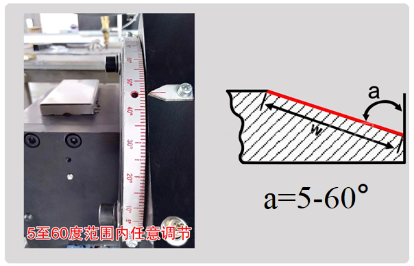
2. The angle range of the bevel can be adjusted freely within the range of 5°to 60°
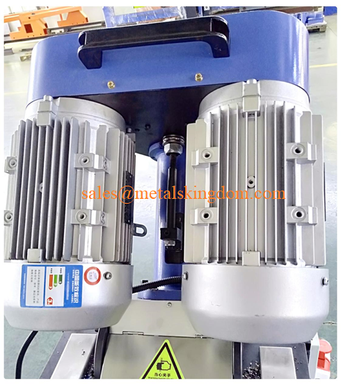
3. Rear mounted Reducer is beneficial for processing narrow plates and is more stable and safe;
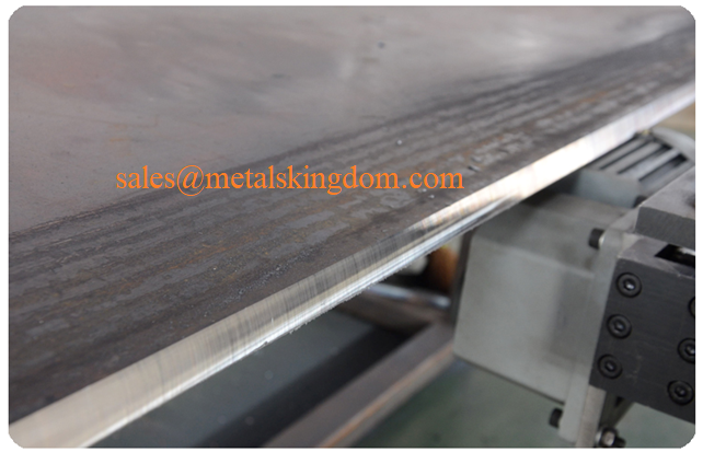
4. The surface smoothness of the processed bevel reaches Ra3.2-6.3, fully meeting the welding requirements of pressure vessels;
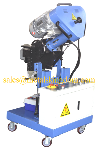
5. Small in size and light in weight, it is a portable automatic walking milling machine and also a moving and portable beveling machine;
6. Cold cutting bevel processing does not change the hardness of the material, and there is no oxide layer on the bevel surface;
1.Product Introduction
This series of beveling machines is used for pre welding metal plate beveling. It mainly utilizes the milling principle to mill and cut the edges of the steel plate at the desired angle to obtain the required beveling for welding. It solves the disadvantages of high manual intensity, non-standard angles, rough slopes, and high working noise in flame cutting, polishing machine grinding processes, significantly reducing oxygen and acetylene gas energy consumption and labor costs. More effectively avoiding the disadvantages of deformation and hardness degeneration of the board after flame cutting; This machine can automatically walk according to the edge of the material, with convenient angle adjustment, easy operation, high efficiency, environmental protection, precise angle, smooth surface, and particularly outstanding characteristics for stainless steel processing.
Mainly used for ordinary structural steel, cast iron, hard plastics, stainless steel, non-ferrous metals and other materials in shipbuilding, metallurgy, pressure vessels, steel structures, petrochemicals, power, heavy industry, mechanical processing plants, mining and aerospace welding fields.
Specializing in stainless steel (pressure vessel) bevels.
2. Product features
2.1 Suitable for processing workpiece materials with high rigidity, hardness, and heat resistance;
2.2 The angle range of the bevel can be adjusted freely within the range of 5°to 60°;
2.3 Rear mounted Reducer is beneficial for processing narrow plates and is more stable and safe;
2.4 The surface smoothness of the processed bevel reaches Ra3.2-6.3, fully meeting the welding requirements of pressure vessels;
2.5 Small in size and light in weight, it is a portable automatic walking milling machine and also a moving and portable beveling machine;
2.6 Cold cutting bevel processing does not change the hardness of the material, and there is no oxide layer on the bevel surface;
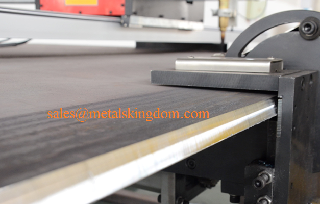
3. Product Structure
Electrical control section, dual main motor section, feed motor section, angle adjustment section, bevel surface adjustment section, height adjustment section, thickness adjustment section, waste cutting material collection section.
4. Configure cutting tools

Note: For other angles, please contact our company.
5. Selection parameters
Electric model | Processing range (mm) | Wall thickness (mm) | Cutterhead speed R/min |
ISE-30 | Φ16-28 | ≤15 | 60 |
ISE-80 | Φ28-76 | ≤15 | 50 |
ISE-150 | Φ65-159 | ≤15 | 35 |
ISE-250 | Φ80-240 | ≤15 | 16 |
ISE-250-2 | Φ80-240 | ≤75 | 16 |
ISE-350 | Φ150-330 | ≤15 | 14 |
ISE-350-2 | Φ150-330 | ≤75 | 14 |
ISE-426 | Φ250-426 | ≤15 | 10 |
ISE-426-2 | Φ250-426 | ≤75 | 10 |
ISE-610 | Φ300-600 | ≤15 | 8 |
ISE-610-2 | Φ300-600 | ≤75 | 8 |
ISE-850 | Φ600-820 | ≤15 | 6 |
ISE-850-2 | Φ600-820 | ≤75 | 6 |
6. Product composition
6.1 Electric motor: It is a single-phase electric motor and is made into a self ventilated protective type. The casing and handle cover are made of thermoplastic engineering plastic, and thermosetting engineering plastic is pressed between the armature shaft and the iron core to form a double insulation structure.
6.2 Body: The box is equipped with a one stage gear reduction mechanism.
6.3 Feed device: Connected by fine thread, nut and core shaft thread, rotate the nut to complete axial feed.
6.4 Clamping device: internal expansion clamping.
6.5 cutterhead: The overall cutterhead is connected to the spindle.
6.6 Tools: Various types of tools.
7. Usage method
7.1 Select the corresponding tensioning block according to the inner diameter of the pipe, install it in the groove of the support shaft and the stopper plate, and connect it with the tension rod and the support shaft with a spring.
7.2 Insert the installed support shaft assembly into the beveled pipe, use a hand to rotate the square head of the pull rod, and firmly fix the support shaft assembly back onto the beveled pipe.
7.3 Install the machine body on the support shaft and rotate the feed handle to screw the internal thread of the machine body into the thread of the support shaft.
7.4 Install the blade and clamp it in the groove of the cutter head with screws according to the diameter of the pipe. Note: Use an alloy blade to cut the gas cut section, and then use a high-speed steel blade for cutting.
7.5 Install the motor, insert the tapered gear shaft into the tapered hole of the motor, and then insert it into the motor interface hole of the beveling machine, and tighten it with screws.
7.6 Connect the power supply to 220V and perform a jog test run. After the machine runs smoothly, start rotating the feed handle for bevel processing. Be careful not to feed too quickly when there are gas cutting marks to prevent cutting or damage to the machine. This machine is equipped with three types of cutting tools: 0 º, 30 º, and 37 º, and the user can customize the bevel form.
7.7 After the bevel processing is completed, cut off the power, clean the dirt on the machine body, add oil and put it into the packaging box.


