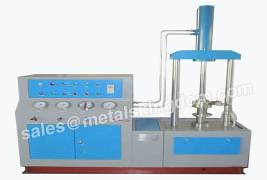
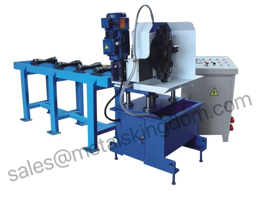
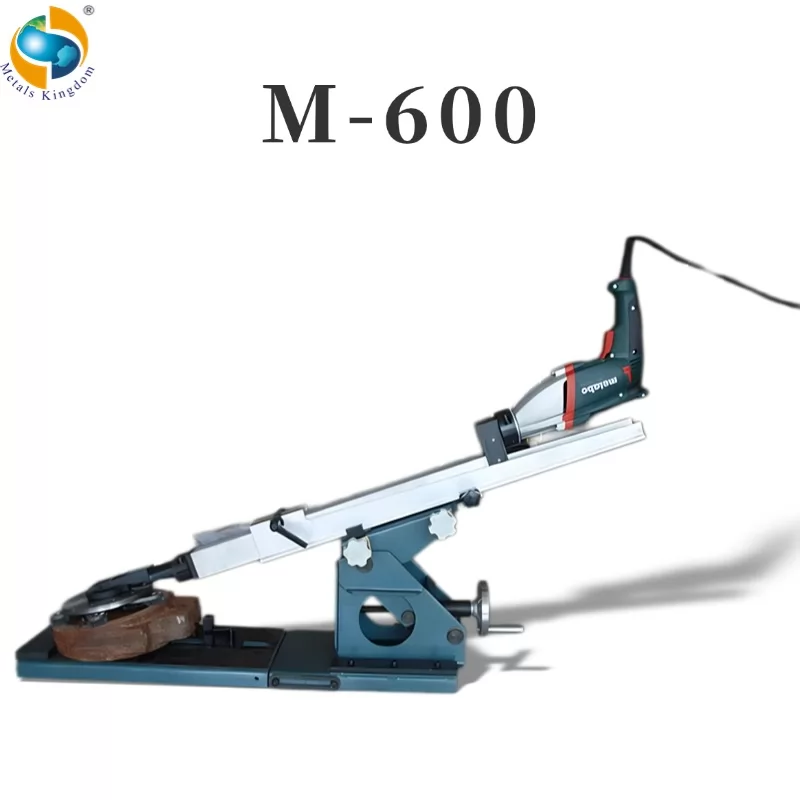
Valve test equipment is suitable for the through-welded and through-flange connection type valves to be sealed and tested before entering the factory, before entering the warehouse or after installation after repairing. It is applicable to the shell test, seal test (low-pressure seal test and high-pressure seal test), and upper seal test (IS05208) of GB4981 to avoid unqualified valves from entering the construction site.
Valve testing machine features simple operation, safe and reliable, and sensitive test.
The precautions for using the valve testing table are as follows
1. Change hydraulic oil regularly
The hydraulic oil needs to be checked and replaced regularly; the condition of the hydraulic oil should be regularly paid attention to and checked. The replacement period of hydraulic oil is generally changed once a year; when due to water intake, high temperature, high humidity, and dust, the oil change period should be shortened.
Method: Open the oil drain plug to drain the oil, then open the upper cover of the fuel tank, and clean the oil injection filter (120 mesh) and the inlet filter. Clean the bottom of the tank.
2. Clean the filter frequently (regularly).
3. Pay attention to the oil level and maintain the oil level.
4. When the oil pump starts and stops, the pressure adjustment switch should be adjusted to the minimum.
5. The maximum pressure in the tubing is less than 25MPa. High-pressure water pipe, the maximum pressure in the pipe can reach 92IPa. Therefore, when the system needs maintenance, it must be shut down for maintenance. When starting up for the first time, all personnel should not face high-pressure water pipes.
6. Exposed oil pipes and water pipes are not allowed to withstand external impact.
7. Connect the power supply for the first time, open the cover of the electrical box, and adjust the steering of the motor (from the fan end of the motor, the clockwise rotation of the motor shaft is the correct steering).
8. When turning off the power, the pressure of the hydraulic system should be adjusted to below 2MPa.
9. The power supply is a three-phase four-wire system, that is, three of the four power wires are connected to the live wire, and the phase voltage is 380V. The other one must be connected to the neutral wire (not the ground wire), and the three live wires are 220V relative to the neutral wire.

Valve Testing Table
Test procedure of valve test bench
1. Valve tightness test.
① Clamp the valve under test.
②Close the right pressure relief valve, turn on the low-pressure water pump switch, until the water flows from the hydraulic outlet, close the right pressure relief valve until the pointer of the gauge starts to move, and close the low-pressure water pump.
③Close the valve door opening and closing parts.
④ Press the boost switch, and then turn the pressure adjustment switch clockwise to make the test pressure gauge reach the value to be tested. According to GB4981 and S05208-1982 standard test pressure should be equal to 1.1 times the maximum allowable working pressure at 20C. The test pressure according to the ZBJ16006-90 standard should be equal to 1.1 times the 38C inch nominal pressure. If there are no special requirements, the pressure in the pressurization process can be checked according to the table in No.4.
⑤We judge whether the tested valve is qualified by the pressure drop during the test duration. There are two test pressure gauges on the operation panel, the fast full scale is 10MPa, and the other full scale is 60MPa. The use of two watches is beneficial to improve the measurement accuracy at low pressure. But it must be noted that when the test pressure is greater than 6MPa, the low-pressure meter switch must be closed tightly to prevent the low-pressure meter from being damaged.
⑥. Open the left pressure relief switch to return the test pressure to zero. Then turn the pressure adjustment knob counterclockwise to make the system pressure less than 0.5MPa.
⑦ Press the release button, turn the pressure adjustment knob clockwise to release the valve under test], and then turn the pressure adjustment switch counterclockwise to make the system pressure less than 0.5MPao. Lift the valve under test. This completes the inspection of a valve.
2. Test the strength of the valve housing and the sealing performance of the upper seal
①. Select the corresponding sealing disc according to the tested valve diameter and connection form.
②. Place the valve under test between the two sealing discs, and the valve outlet rushes towards the movable sealing disc. Then press the "clamp" button to clamp the valve under test. The clamping force is checked according to the comparison table.
③. Open the valve door opening and closing parts; open the left pressure relief to inject water into the tested valve door until water flows out from the pressure relief hole. Then close the pressure relief valve.


